 English
 русский
 Español
 عربى
Do Diesel Generators Produce Carbon Monoxide? CO Facts and Safety Basics
A 400 kVA standby set sits in a walled service yard between an office block and a loading dock. On a Friday evening the utility feed drops, the set fires up, and it runs for six hours. Nothing looks wrong from the outside. What nobody notices is a split bellows in the exhaust line under the acoustic canopy, and a rooftop air handling unit drawing fresh air from exactly the corner of the building where the plume drifts. Two staff working late on the floor below develop headaches and nausea within the hour and go home early, blaming the weather.
Diesel generators do produce carbon monoxide. That part is not in dispute and never has been. The question worth answering is how much they produce, which operating conditions push the number upward, and what has to happen between the tailpipe and a human lung for a manageable emission to become a medical emergency. In field investigations, almost every serious incident traces back to the third item rather than the first.
The Direct Answer: Yes, and Concentration Is What Decides the Outcome
Every diesel generator produces carbon monoxide, because CO is an unavoidable intermediate product of burning a hydrocarbon fuel. There is no combustion engine, no fuel type, and no aftertreatment package that removes the gas entirely. What differs between a well-installed set and a dangerous one is the concentration at the point a person breathes, and that is a function of dilution, not of engine design.
The raw numbers help frame the problem. Undiluted diesel exhaust typically carries CO at roughly 0.05% to 0.5% by volume, which is 500 to 5,000 parts per million. The occupational exposure limit for an eight-hour shift is 50 ppm. That means a raw concentration of 1,000 ppm needs about 20 volumes of clean air mixed into it before the mixture drops to the limit; a 5,000 ppm stream needs roughly 100 volumes. In an open yard with a breeze, a hundredfold dilution happens within a few meters. In a closed plant room, a basement, or the lee of a building where the plume curls back on itself, it may not happen at all.
This is why the same generator model can be entirely safe on one site and lethal on another. The engine did not change. The air around it did.
Why a Compression-Ignition Engine Still Forms CO
Diesel engines are lean-burn machines by nature. Air is drawn in unthrottled, compressed to a ratio of roughly 14:1 to 18:1, and heated to the point where injected fuel ignites on contact. Across most of the operating map there is far more oxygen present than the fuel can consume, with lambda values from 1.3 at full load up to 5 or 6 at light load. In an oxygen-rich environment at high temperature, CO readily oxidizes to CO2, which is the main reason diesel exhaust is comparatively CO-poor.
The catch is that combustion is not uniform. Fuel is injected as a spray, and inside each spray plume there is a short-lived fuel-rich core where oxygen is scarce and the local mixture is far from lean. That core is where CO and soot are born. Most of the CO burns up downstream as it mixes with surrounding air, but a fraction escapes the cycle, particularly when the mixing process is disturbed.
Lean Operation Keeps CO Low Compared With Spark-Ignition Engines
A gasoline or gas engine running at stoichiometry with power enrichment can push CO to 1%–3% of raw exhaust, and beyond 5% when the choke is on or the air filter is blocked. Diesel rarely exceeds half a percent. Published emissions data and stack testing consistently place diesel an order of magnitude below gasoline on this metric. The practical consequence is that diesel gets a reputation for being "the safe one," and that reputation is partly deserved at the tailpipe and completely misleading at the point of exposure.
The Conditions That Push CO Upward
CO output is not a fixed property of the engine; it moves with the operating state. The conditions that reliably raise it are well documented in service literature:
- Cold starting, when cylinder walls are cold, atomization is poor, and misfire produces a burst of CO and unburned hydrocarbons for the first minutes of running.
- Very light load, below roughly 30% of rated output, where combustion temperatures fall and the engine runs into the wet-stacking regime.
- Restricted intake air from a clogged filter, a collapsed hose, or a blocked canopy louver, which effectively enriches the mixture.
- Worn or fouled injectors that deliver poor spray patterns and large droplets that cannot burn completely.
- Charge-air leaks on turbocharged units, causing over-fuelling relative to available oxygen.
- Excessive exhaust backpressure from a crushed pipe, a blocked silencer, or an undersized stack.
Aftertreatment Reduces CO but Does Not Replace Venting
An oxidation catalyst placed in the exhaust stream can cut CO by 70% to 90% once it reaches operating temperature, and it does nothing during the cold-start window when concentrations are highest. Diesel particulate filters and selective catalytic reduction systems target soot and nitrogen oxides respectively; they are not CO safety devices. Treating aftertreatment as a substitute for proper exhaust routing is a common and dangerous assumption, because a catalyst that has failed, been removed, or never reached light-off leaves the full raw concentration in the pipe.
Typical CO Concentrations: Diesel Compared With Other Fuels
Buyers often ask for a single figure. The honest answer is a range, because load, tuning, and aftertreatment move the number considerably. The table below gives indicative raw exhaust concentrations at the tailpipe for the fuels most often encountered in standby and prime power applications.
| Fuel and combustion type | Typical CO in raw exhaust | Practical risk notes |
|---|---|---|
| Diesel, compression ignition | 0.05%–0.5% (500–5,000 ppm) | Lowest CO of the liquid fuels per unit of energy; haze or smoke is a poor indicator of CO level |
| Biodiesel blends, compression ignition | Broadly similar to diesel, sometimes slightly lower CO | Higher nitrogen oxides; cold-start behaviour can be worse with high blend ratios |
| Gasoline, spark ignition at stoichiometry | 0.5%–3% (5,000–30,000 ppm), higher under enrichment | Cold-start and choke enrichment create very high short-term peaks |
| Natural gas or LPG, spark ignition | 0.1%–1% (1,000–10,000 ppm) | Highly dependent on fuel-air setup and lambda control; unburned fuel adds a second hazard |
Two conclusions follow from the table. First, diesel is genuinely the lower-CO option among reciprocating engines, which is one reason it dominates data centre and industrial standby duty. Second, "lower" is not "low." A 5,000 ppm stream is a hundred times the occupational limit before dilution, and an enclosed space offers very little dilution.
Dilution, Venting, and the Geometry of the Exhaust Plume
Carbon monoxide has a density of about 0.97 relative to air, which makes it very nearly neutrally buoyant. It does not sink into basements the way propane does, and it does not rise clear of a roof the way hot flue gas from a boiler might. It travels with whatever air mass carries it. That single physical fact explains most of the site failures seen in the field: the plume goes where the wind and the building shape send it, and a termination point chosen for convenience rather than for aerodynamics will eventually deliver exhaust somewhere it should not go.
Building wakes are the main culprit. When wind hits a structure it creates a low-pressure recirculation zone on the leeward side, and any exhaust discharged into that zone is pulled back toward the building, often directly into rooftop air intakes, louvres, or open windows. A stack that clears the roof by half a meter may be entirely inside the recirculation zone and therefore worse than useless.
Stack Height and Termination Points
General engineering practice, echoed in manufacturer installation manuals and mechanical codes, points to a few consistent rules. Discharge the exhaust above the roofline and above the recirculation zone, which in practical terms often means at least 3 m above the roof surface and higher than any nearby structure or intake. Keep horizontal separation from doors, operable windows, and fresh-air intakes, with 10 m being a commonly applied figure where local codes are silent. Maintain a discharge velocity high enough to give the plume upward momentum, typically in the 10–20 m/s range at the stack exit, rather than letting it dribble out at low speed. And always check the manufacturer's minimum backpressure allowance before adding length or elbows to make the routing work.
Enclosure Airflow and the Recirculation Trap
Acoustically enclosed and containerised sets introduce a second layer of complexity. The canopy needs two separate air paths: combustion air for the engine, and cooling air for the radiator. If the exhaust gas outlet and the cooling air intake are close together, hot exhaust gets drawn back into the enclosure, raising intake air temperature and reducing oxygen density. The engine then over-fuels relative to the oxygen available, and CO rises while power falls. Good canopy design keeps the two paths on opposite faces, uses separate penetrations, and seals the exhaust penetration with a high-temperature boot rather than a loose plate.
Containerised packages deserve particular attention because they concentrate every hazard into a small footprint. For projects where a self-contained, weather-protected package suits the site layout, a purpose-built enclosure with defined air paths is far easier to specify correctly than a modified shipping container.
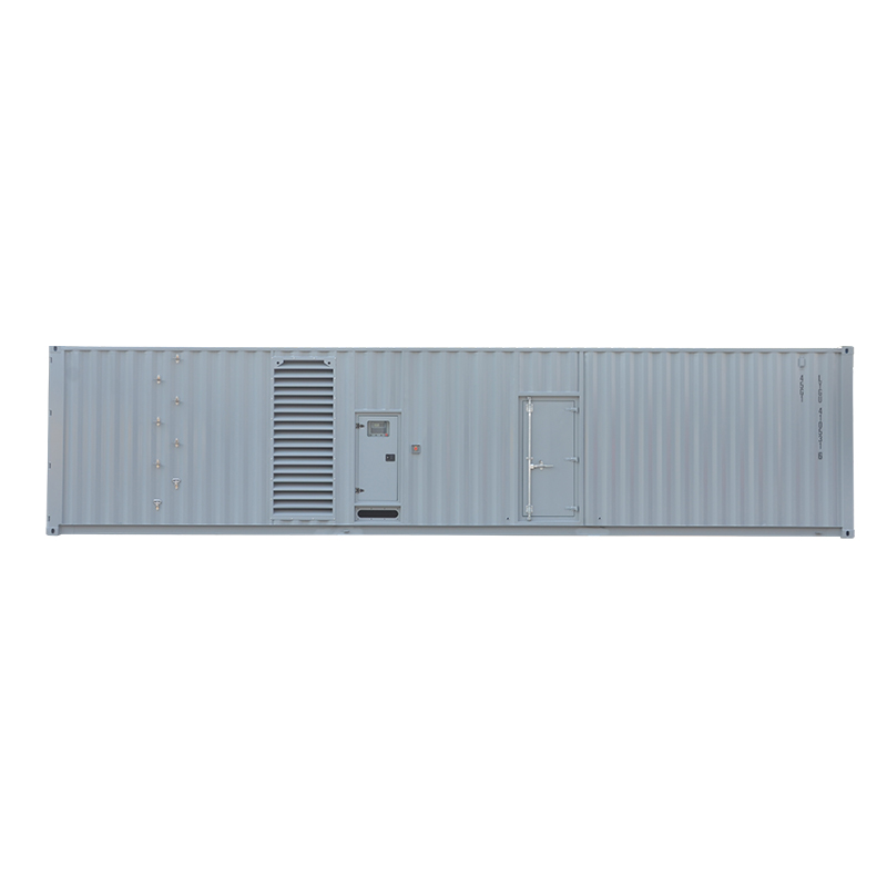 Containerized Diesel Generator Sets, Container Type SeriesPurpose-built containerized power from 1000–4000kVA with CSC-compliant enclosures, acoustic airflow design, and weather-protected transport options for sites needing defined air paths.View Product →
Recirculation Traps That Appear on Real Sites
Commissioning photographs repeatedly show the same handful of problems. A temporary tarpaulin wrapped around a set for weather protection during construction, covering the exhaust exit. A parapet wall added after the generator was installed, now trapping the plume at roof level. A stack extended with a flexible hose that sags and points sideways. Delivery vehicles parked against the discharge louvre. Snow accumulation reducing effective stack height. None of these are engine faults, and all of them can turn a compliant installation into an exposure event within one test run.
Load, Maintenance, and Site Conditions That Change Emissions
Standby generators spend most of their lives at zero load and most of their running hours at partial load, which is precisely where combustion quality degrades. The factors below are the ones that most often move CO away from the commissioning baseline.
| Factor | Effect on CO output | Field check |
|---|---|---|
| Sustained load below 30% of rating | Lower combustion temperature, incomplete burn, wet stacking, rising CO and hydrocarbons | Load history log; exhaust port temperature; oil analysis for fuel dilution |
| Cold ambient start | Short high-CO spike during the first minutes, white smoke | Intake air heater or jacket water heater operation; start-time records |
| Clogged air filter or blocked louvre | Enrichment and higher CO, often with black smoke under load | Restriction indicator; differential pressure across the filter |
| Worn or fouled injectors | Poor atomization, higher CO and particulates | Injector return flow test; exhaust gas analysis at several load points |
| Charge-air or boost leak | Over-fuelling relative to oxygen, CO climbs with smoke | Boost pressure against the specification at rated load |
| Excessive exhaust backpressure | Reduced scavenging, higher CO and higher exhaust temperature | Pressure gauge at the test port compared with the engine maker's limit |
| Altitude above roughly 1,000 m | Lower oxygen density acts like enrichment; CO rises with derating error | Site altitude against the derating table used for the power rating |
| Fuel quality problems, water or high viscosity | Irregular combustion, misfire, CO spikes | Fuel sampling; filter inspection; water separator drains |
Load banking is the most effective single countermeasure. An annual run of two hours at 80% load or above burns off accumulated deposits, restores combustion quality, and gives a stable reference point for exhaust gas analysis. Sets that are only ever exercised at no load tend to drift upward in CO year after year without anyone noticing, because nothing fails loudly.
What the Exposure Limits Actually Mean on Site
Numbers only become useful when they connect to a decision. The table below sets out the limits most often cited in specifications, safety cases, and insurance surveys.
| Reference | Limit | Averaging period and notes |
|---|---|---|
| Occupational exposure limit (US OSHA) | 50 ppm | Eight-hour time-weighted average for general industry |
| Recommended exposure limit (US NIOSH) | 35 ppm | Eight-hour average, with a 200 ppm ceiling value |
| Threshold limit value (ACGIH) | 25 ppm | Eight-hour average; widely adopted in corporate specifications |
| World Health Organization, 24-hour guideline | 7 mg/m³ (approximately 6 ppm) | Ambient air quality guidance for the general population |
| World Health Organization, 1-hour guideline | 35 mg/m³ (approximately 30 ppm) | Short-term exposure guidance |
| Immediately dangerous to life or health (NIOSH) | 1,200 ppm | Ceiling value for escape planning and emergency response |
The gap between 50 ppm and 1,200 ppm looks reassuring until you consider how quickly a leaking exhaust can fill a small room. A 20 m² plant room with 2.5 m ceilings holds 50 m³ of air. A modest leak passing a fraction of the exhaust flow into that space can push concentrations into the hundreds of ppm within minutes, and the room is unbreathable long before anyone notices a smell, because there is no smell to notice.
Symptoms at Realistic Concentrations
Carbon monoxide binds to haemoglobin with an affinity roughly 200 times that of oxygen and shifts the oxygen dissociation curve, which is why symptoms appear at concentrations far below those that would reduce oxygen supply by simple displacement. Recognising the progression matters for anyone who works near generator plant.
| Concentration | Typical effect |
|---|---|
| 35–100 ppm | Headache and fatigue after several hours of exposure |
| 100–200 ppm | Headache within one to two hours, dizziness, reduced judgement |
| 200–400 ppm | Headache, nausea, and dizziness within one to two hours; life-threatening after about three hours |
| 400–800 ppm | Severe headache, confusion, nausea within 45 minutes; collapse within two hours |
| 800–1,600 ppm | Collapse within 20 to 60 minutes; risk of death within one to two hours |
| Above 3,200 ppm | Death within minutes |
The clinical picture is easy to misread. Headache, nausea, and fatigue are routinely attributed to a virus, a long shift, or bad air conditioning, and the association with a generator that started two hours earlier is never made. In shared buildings, multiple occupants reporting the same symptoms in the same time window is the strongest early signal available.
High-Risk Applications Worth Examining Closely
Some duty profiles concentrate the risk. They share a common feature: the generator is close to people, and the exhaust has a plausible route back into occupied space.
Data centres and telecom sites are the classic case. Banks of four to eight large sets sit in a rooftop yard or a ground-level compound, often on the same roof as air-cooled chillers and air handling units. Monthly testing under NFPA 110 requirements means the plant runs when the building is fully occupied. When six plumes merge in a light crosswind and drift across a chiller bank, the intake that serves the white space pulls in diluted exhaust. Commissioning wind studies and post-installation tracer testing exist precisely because intuition about plume behaviour is unreliable.
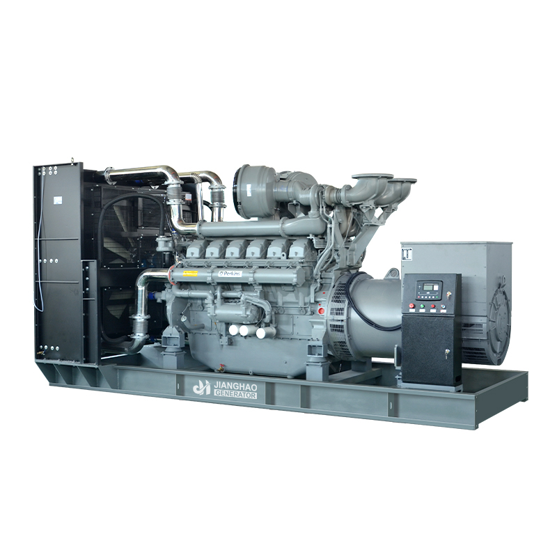
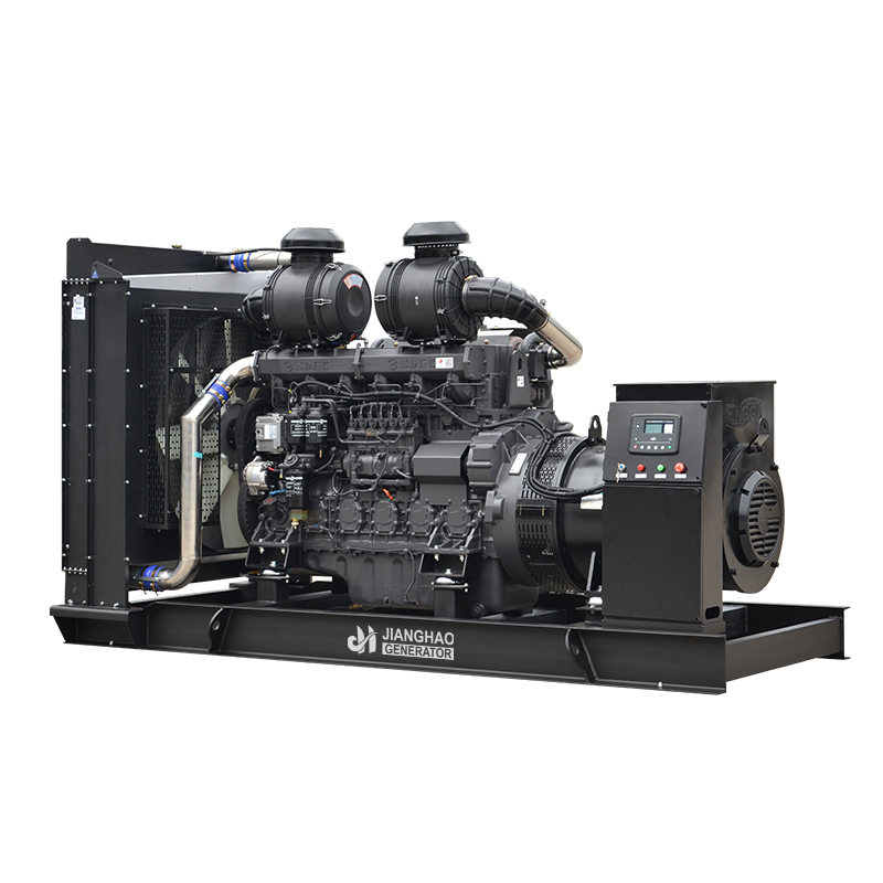
 Diesel Generator Set Categories by Engine, Power and StructureBrowse diesel, gas and marine generator set categories from 8–4000kVA, including open, silent, trailer and container types for varied backup and industrial power.View Product →
Larger facilities also tend to distribute power over longer distances, which pushes the electrical design toward higher generation voltages and dedicated step-up arrangements rather than LV cable runs. That changes the plant layout and often the physical position of the exhaust termination.
High-voltage generator sets are specified for exactly this kind of distribution architecture, and the exhaust design has to be reviewed at the same time as the single-line diagram, not afterwards.
Marine installations present a different geometry. A vessel at anchor runs its auxiliary set for hotel load, and the exhaust discharges at the hull side or under the swim platform. Wind over the superstructure creates a low-pressure region at the stern, and exhaust can be drawn back into the cabin through open ports or the air conditioning intake, a pattern long recognised in boating safety literature. Rafting alongside another vessel concentrates both plumes in the same space between hulls. Generator exhaust is implicated in a meaningful share of recreational boating CO incidents.
Mining and tunnelling work puts diesel equipment in semi-enclosed spaces where ventilation is engineered rather than natural. The ventilation plan has to account for all the engine exhaust in the heading, not just the largest unit, and CO is one of several gases monitored. Trailer-mounted sets used for construction power bring the same issue to the surface: the exhaust outlet ends up a few meters from a site cabin door or a fresh-air intake because that was the only level spot available.
Design and Specification Measures That Reduce Risk
Most of the practical protection is decided long before the engine is ordered. The following sequence reflects how the issue is usually handled on projects that end up with defensible installations.
- Fix the exhaust route first. Decide where the termination point will be, what it will discharge into, and what is downwind in the prevailing wind directions across the year, not just on the day of the site visit.
- Size the stack for velocity and height, not for convenience. Check backpressure against the engine maker's limit once the full run, silencer, and bends are counted.
- Separate combustion air from cooling air, and separate both from the exhaust gas exit. Verify that the canopy cannot ingest its own discharge.
- Specify gas detection with an alarm and, where the application allows, a shutdown interlock. Commercial sensors to UL 2075 are appropriate for plant rooms; residential alarms to UL 2034 belong in living accommodation, not in an engine hall.
- Provide remote annunciation for exhaust temperature, backpressure, and detector status so that a developing fault is visible before it becomes an exposure.
- Include a load bank connection as standard, so that annual high-load testing is simple enough to actually happen.
- Require commissioning exhaust gas analysis at 25%, 50%, 75%, and 100% load, with the results recorded as the baseline for future comparison.
- Set out the O&M requirements in the handover documentation, in the language the operating team actually reads.
Acoustic requirements often collide with these measures, because the quietest canopy is the one with the fewest openings. A well-engineered silenced package resolves the conflict through baffled paths rather than by sealing the enclosure, and the specification should state the required airflow and the permitted exhaust termination geometry rather than only a sound pressure level at one metre.
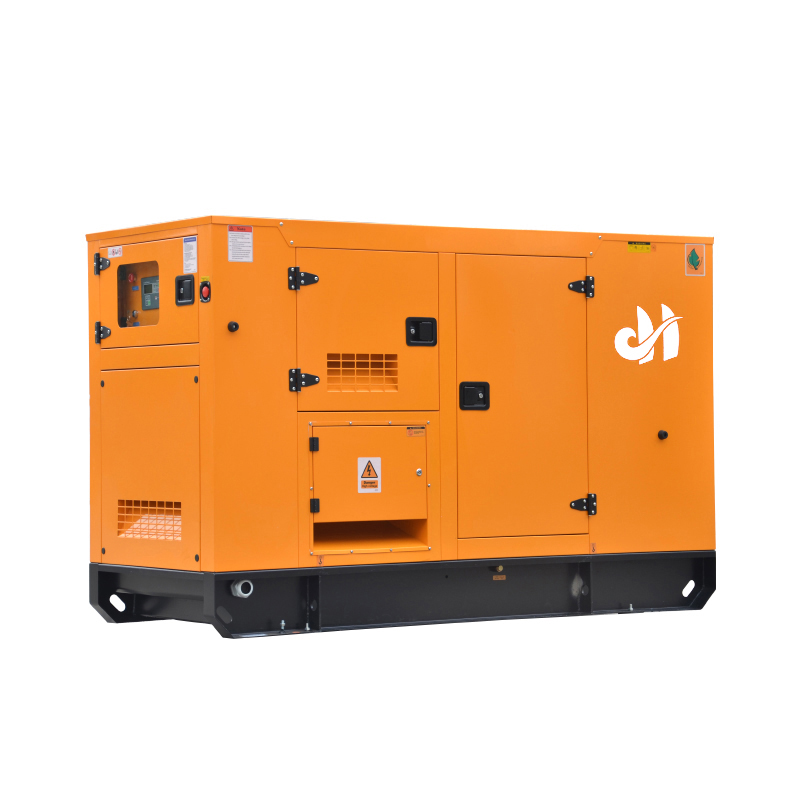
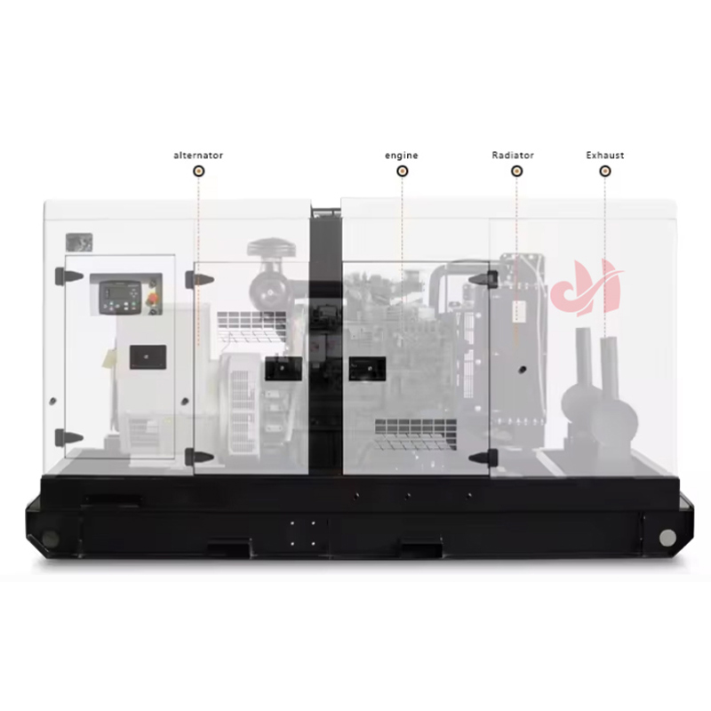 Silent Diesel Generator Sets, 8–4000kVAFor noise-sensitive sites, these 8–4000kVA silenced sets use enclosed canopies, sound-absorbing materials and mufflers to reduce noise while maintaining output.View Product →
Where the site layout is unusual, a standard catalogue unit may not fit at all, and a project-specific arrangement is the more honest route. Custom engineering of the enclosure, exhaust routing, and control interface is often the difference between a compliant installation and a compromise that needs remedial work after commissioning.
Custom generator set design is the appropriate route when stack height, footprint, or air path constraints cannot be met by a catalogue configuration.
Maintenance and Testing Routines That Keep CO Under Control
Once an installation is correct, keeping it correct is mostly a matter of inspection discipline. Exhaust systems fail at joints, bellows, and gasket faces, and they fail slowly enough that the first visible sign is often a soot streak.
Monthly
- Walk the full exhaust path and look for soot staining, loose clamps, cracked flexible sections, and corroded flanges.
- Confirm the termination point is clear of tarpaulins, stored materials, vehicles, snow, or new construction.
- Run the set on load, ideally at 30% or more, and observe exhaust colour and steadiness at the stack.
- Bump-test CO detectors with calibration gas and record the result.
Annually
- Analyse exhaust gas composition at multiple load points and compare with the commissioning baseline. A rising CO trend at identical load is an early indicator of injector, air filter, or turbo problems.
- Measure exhaust backpressure at the test port and compare with the engine maker's maximum.
- Load bank for at least two hours at 80% load or above to clear wet stacking.
- Service injectors, verify valve lash, and check charge-air integrity on turbocharged units.
- Replace or recalibrate CO sensors according to the manufacturer's stated sensor life, typically two to five years.
Records matter more than most operators expect. Without a baseline, a reading of 400 ppm in the stack tells you nothing; with a three-year history at the same load point, the same reading tells you that something has changed and where to look.
Emergency Response When an Alarm Sounds
The response sequence is short and should be rehearsed rather than improvised. If a CO detector activates, treat it as a real event until proven otherwise. Move people out of the affected area and into fresh air, opening doors and windows from outside on the way if it can be done without delay. Do not switch electrical equipment on or off inside the space, because a spark in an atmosphere carrying unburned fuel is a second hazard. Call the emergency services, account for everyone who was in the building, and tell the responders that a generator is running and where its exhaust terminates.
Anyone showing headache, dizziness, confusion, nausea, or drowsiness should be assessed by medical staff even if they feel better after reaching fresh air. Carbon monoxide has a half-life of roughly four to five hours on room air, about an hour on high-flow oxygen, and considerably less under hyperbaric treatment, so symptoms can recur as exposure resumes or as the patient exerts themselves. Do not re-enter the space until the source has been found, the exhaust path has been inspected, and the atmosphere has been measured with a calibrated instrument.
Resetting a detector without finding the cause is the single most common error in the aftermath of an incident. The alarm did its job; the fault is still in the pipe.
Diesel generators produce carbon monoxide at concentrations that are modest compared with gasoline engines and entirely capable of killing someone in a confined space. Both halves of that sentence are true at the same time, and most of the confusion in the market comes from quoting only one of them.
For anyone specifying, installing, or operating this equipment, the sequence that works is consistent: accept that CO is present, quantify it at the tailpipe, and then design the route from the stack to the open sky so that dilution does the rest. A 20 kVA set with a stack that discharges into a window is more dangerous than a 2,000 kVA set with a properly engineered termination. The engine sets the emission rate; the installation sets the exposure.